Ethernet header
The Ethernet header is composed of the following fields, as seen below:
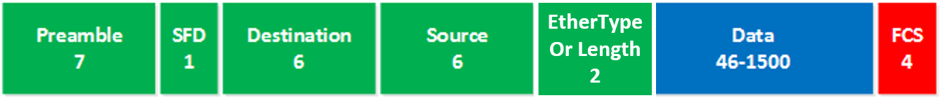
- Preamble: this is a 7-byte pattern of ones and zeroes and is used for synchronization.
- SFD: the “start frame delimiter” marks the end of the preamble and tells the receiver that the next fields will be the actual Ethernet frame, starting with the destination field.
- Destination: this is the destination MAC address of the receiver.
- Source: the source MAC address of the device that sent the frame.
- EtherType or Length:
- For Ethernet II frames, this is the EtherType field which tells us what is carried inside the Ethernet frame. An IPv4 packet, IPv6 packet or something else.
- For [IEEE] 802.3 frames, this is the Length field which indicates the length or size of the Data or payload in bytes
- For more information, take a look at Ethernet frame types
- Data: this carries the actual data that we are trying to transmit, for example an IPv4 packet.
- FCS: the frame check sequence helps the receiver to figure out if the frame is correct or corrupt.
The total size of the header is 22 bytes. However, strictly speaking, the Preamble and the SFD are considered part of the Physical Layer encapsulation. This is because these fields are used primarily for the synchronization of the received frames, and don't actually contain any information about the frame itself.
Note that when it comes to MTU settings, the Preamble and SFD are not counted within the size of the frame, so a regular Ethernet frame is considered to have a header size of 14 bytes and a payload size of 1500 for a total of 1514.
Links
https://networklessons.com/cisco/ccna-200-301/introduction-to-ethernet#Data_Link_Layer https://en.wikipedia.org/wiki/Ethernet_frame#Frame_%E2%80%93_data_link_layer
Links to this page:
- Ethernet - role of FCS field
- Ethernet frame types
- Ethernet
- Interface - unknown protocol drops
- MAC address table populated using source address field
- MAC address table
- MTU - Interface MTU vs IP MTU
- MTU - MSS and Jumbo Frames
- MTU - Understanding L2 MTU and Frame Handling in Network Switches
- Ping - specifying size
- Ping - sweep range of sizes
- QoS - CoS to DSCP and DSCP to CoS mapping
- STP how a switch identifies a BPDU
- Security - storm control algorithm
- Switching - cut through
- Switchport - IEEE 802.1q
- Switchport - ISL
- Switchport trunk