Network - Example of communication, encapsulation, and decapsulation, between hosts
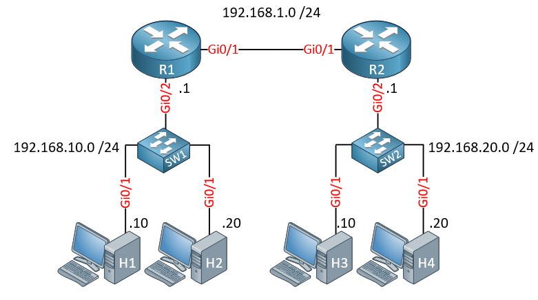
When communication takes place between two hosts, there is communication that takes place at various levels of the OSI Model. This example shows how communication takes place between two hosts while examining the encapsulation and decapsulation process. For this example, we'll be looking at hosts with IPv4 addressing in the following topology:
Communication between hosts in the same subnet
Let's examine the communication between H1 and H2. Let's say that H1 is sharing a file with H2, and a packet is being sent from H1 to H2 containing a part of that file. Let's start by looking at the Transport layer.
Transport Layer
TCP will be used at this layer, and will encapsulate a part of the file into a segment. This segment will have source and destination port numbers indicating the application on each host that is to send and receive the segment.
Network Layer
This TCP segment is then encapsulated into an IP packet. Here the IPv4 header is added which contains the source and destination IPv4 addresses. In this particular case, the addresses used are:
- Source: 192.168.10.10
- Destination 192.168.10.20
Now before further encapsulation, H1 must determine if the destination IP address is on the same subnet or a different subnet. This will determine the destination MAC address that will be used in the Data-Link layer encapsulation process.
The subnet mask information configured on the network interface card (NIC) of H1 includes a subnet mask of 255.255.255.0 or /24. This indicates that H1 belongs to a network with an IP address space ranging from 192.168.10.0 to 192.168.10.255. Using this information, H1 determines that the destination address is in the same subnet, because it too is within this range. Next, ARP is used to determine the next hop MAC address.
Datalink Layer
At this point, H1 knows that the destination address is in the same subnet. So the next step is to determine the MAC address of that host to populate the destination MAC address field of the Ethernet frame. This is done using the ARP protocol. H1 will send out an ARP request for the MAC address that corresponds to the 192.168.10.20 address, the IP address of H2. H2 will respond with the required information, and H1 will encapsulate the frame with this info.
Physical Layer
The frame is then converted to the appropriate voltage signals or light pulses on the wire or fiber using the appropriate Ethernet encoding methodology. SW1 will receive this frame, take a look at the destination MAC address, and using the MAC address table will determine out of which port to send it so that H2 will receive it.
H2 receives data
Once H2 receives this data, it begins the decapsulation process:
- It decapsulates the frame and examines the destination MAC address and determines that the frame is indeed addressed to itself
- It decapsulates the packet and examines the destination IP address and determines that the packet is indeed addressed to itself.
- It decapsulates the segment and examines the destination port and determines the application for which the segment is destined.
Once fully decapsulated, the data is then reassembled with the rest of the segments into the original file that was sent.
Communication between hosts in different subnets
Let's examine another scenario where we have communication between H1 and H3, which are on different subnets. What does this communication look like?
Transport Layer
As before, TCP will be used at this layer, and will encapsulate a part of the file into a segment. This segment will have source and destination port numbers indicating the application on each host that is to send and receive the segment.
Network Layer
This TCP segment is then encapsulated into an IP packet. Here the IPv4 header is added which contains the source and destination IPv4 addresses. In this particular case, the addresses used are:
- Source: 192.168.10.10
- Destination 192.168.20.10
Now before further encapsulation, H1 must determine if the destination IP address is on the same subnet or a different subnet. This will determine the destination MAC address that will be used in the Data-Link layer encapsulation process.
The subnet mask information configured on the network interface card (NIC) of H1 includes a subnet mask of 255.255.255.0 or /24. This indicates that H1 belongs to a network with an IP address space ranging from 192.168.10.0 to 192.168.10.255. Using this information, H1 determines that the destination address of 192.168.20.10 is in a different subnet since it is not within the range indicated.
Datalink Layer
At this point, H1 knows that the destination address is in a different subnet. This means that the next hop must be to the default gateway. Remember, the default gateway is where packets must be sent to reach other subnets. So the next step is to determine the MAC address of the router that is acting as the default gateway of the local subnet. This is configured on the NIC of H1. The default gateway is R1 with an IP address of 192.168.10.1
So H1 will send out an ARP request for the IP address of the default gateway. R1 will respond providing its MAC address, and H1 will encapsulate the frame with this MAC address as the destination address. Next, ARP is used to determine the next hop MAC address.
Physical Layer
The frame is then converted to the appropriate voltage signals or light pulses on the wire or fiber using the appropriate Ethernet encoding methodology. SW1 will receive this frame, take a look at the destination MAC address, and using the MAC address table will determine out of which port to send it so that R1 will receive it.
R1 receives data and sends it to R2
Once R1 receives this data, it begins the decapsulation process:
- It decapsulates the frame and examines the destination MAC address and determines that the frame is indeed addressed to itself
- It decapsulates the packet and examines the destination IP address. It uses that IP address to determine where to route the packet using the Routing Table.
- It is sent out of Gi0/1 and sent to R2.
- R2 will do the same process, and will determine that it has a subnet on one of its interfaces that corresponds to the destination address, and will send the packet out of the Gi0/2 interface.
- H2 will then receive the data.
H2 receives data
Once H2 receives this data, it begins the decapsulation process:
- It decapsulates the frame and examines the destination MAC address and determines that the frame is indeed addressed to itself
- It decapsulates the packet and examines the destination IP address and determines that the packet is indeed addressed to itself.
- It decapsulates the segment and examines the destination port and determines the application for which the segment is destined.
Once fully decapsulated, the data is then reassembled with the rest of the segments into the original file that was sent.
Links
https://networklessons.com/cisco/ccna-200-301/introduction-to-the-osi-model https://networklessons.com/cisco/ccna-200-301/ip-routing-explained