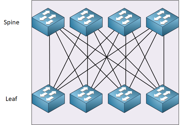
Network Design - Spine and leaf architecture
The spine and leaf architecture describes the way in which the switches are interconnected. It is primarily a physical layer architecture. The distinguishing feature, compared to the more traditional tiered model, is that every spine switch has a physical connection to every leaf switch. There is no specialized configuration on the devices to achieve this architecture.

Even so, there are some guidelines for configuration to keep in mind when implementing such an architecture, but these are not specific to the architecture itself but to general networking best practices.
- Don’t use Spanning Tree Protocol (STP). Ensure that your configuration does not rely on STP to prevent L2 loops, otherwise, you waste available bandwidth by causing all links but one to remain idle
- Configure VLANs only on leaf switches. Spine switches should remain unaware of VLAN configurations. Spine switches should perform routing between the VLANs configured on the leaves.
- Routing protocols configured to function with Equal-cost Multi-path routing should be implemented to ensure the most efficient usage of the multiple uplinks to the spine switches. For extensively large networks, Cisco recommends the use of BGP to ensure the scalability of such networks.
This type of network is sometimes called a Clos network. A “Clos network” refers to a multistage, non-blocking switch architecture designed by Charles Clos in the 1950s for telephone exchanges. Since its original inception, the principles behind the Clos network have been applied to data center architectures, especially for scalable and efficient network switches. The spine and leaf topology is actually a type of collapsed Clos network.